|
|
Biological Small Angle Scattering |
|
|
|
| ATSAS online | Forum | User information | EMBL Hamburg |
|
|
MASSHA manualWritten by P.V. Konarev, M.V Petoukhov and D.I. Svergun. © ATSAS Team, 2003-2009 Table of Contents
ManualModelling of atomic structures and shape analysisMASSHA is a 3D graphic system to display and manipulate atomic structures and low resolution models. The program is coupled with computational modules to allow interactive and automated rigid body refinement against solution scattering data. MASSHA is compiled using Compaq Visual Fortran v. 6.6B with QuickWin graphics library and runs under MS Windows 95/98/NT/2000/XP/Vista or under Windows emulators (like WINE) installed on Linux/MAC. If you use results from MASSHA in your own publication, please cite: MASSHA User Interface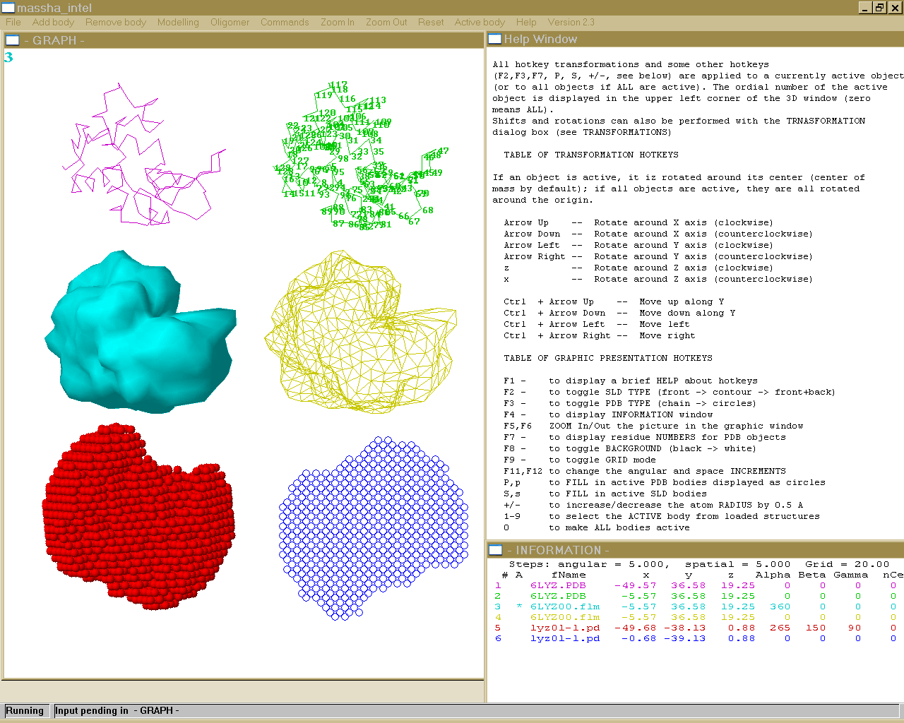 I/O commands for MASSHAFILE FORMATS MASSHA reads two types of models: (a) Atomic structures in a standard ASCII PDB file format (PDB-objects, extensions *.PDB or *.ENT) Those can be atomic structures from the Brookhaven database or e.g. the models produced by the ab inito program DAMMIN. NOTE: MASSHA reads and displays only CA or P atoms!! Support for loading and transformations of atomic models in CIF format is added (starting from ATSAS 3.1.0) !! It is allowed to load up to 20 OBJECTS (BODIES) !! !!The total number of atoms in the loaded files should not exceed 20000 !! !! The total number of atoms in the loaded files is increased to 500000 (starting from ATSAS 3.1.0) !! (b) Low-resolution envelopes represented as surfaces (binary files with the extension *.SLD, SLD-objects). These files are created by the program FLM2SLD from the spherical harmonics files (extension *.flm). The latter files are written on output by the programs SASHA and CRYSOL/CRYSON. The users may directly load an FLM file, in which case FLM2SLD will automatically be invoked by MASSHA LOADING A NEW OBJECT To load a new object, use the ADD BODY option from the main menu. By default, the objects are loaded to their absolute positions as specified in the input file, without any rotation and movement. The geometrical center of an object can be later moved to the origin or to the coordinates specified by the user (see TRANSFORMATIONS) The initial scale of the graphic window is selected using the gabarites of the first body. By default, SLD-objects are rendered as wireframes and PDB-objects as connected C-alpha or P backbones. When launching the program from a console, the PDB or SLD filenames can be added as command line arguments. NOTE: A maximum of nine objects can be displayed simultaneously. REMOVING AN OBJECT To remove the last loaded object from MASSHA, use the REMOVE BODY option from the main menu. Subsequently using this button one can remove objects one by one. To remove all loaded objects at once and to clear the 3D graphic screen use CLEAR submenu option in the FILE menu. PDB FILES SAVING. To save an active PDB-object in its current position use COMMANDS -> Save PDB. The object is saved into a file phsaveX.pdb where X is its number as loaded. If all objects are active ("0" in the upper left corner of the graphic window), all PDB objects will be saved. This option is convenient for saving the results of interactive or automated model building (see RIGID BODY MODELLING). NOTE: (1) The SLD objects are not saved. (2) If the file you loaded is "phsaveX.pdb", the program will name the saved file "phsaveX0.pdb" (3) If one generates the symmetry mates using 'Oligomer - Pn symmetry' menu and wants to save them, then one needs to keep the dialog box (for rigid body modeling) opened and to press '0' (make active all bodies) before going to 'Commands - Save pdb' menu. PICTURE SAVING AND PRINTING. The FILE menu option provides several possibilities of saving graphic or text information. Use PRINT to print the content of a window. Use SAVE SCREEN to create a *.bmp file with the current program image, or use SELECT ALL (for selecting the entire window in graphic form), SELECT GRAPH ( for selecting a rectangular part of the window by double muuse click) or SELECT TEXT ( for selecting the text part of the window). The image will be copied onto a clipboard and can further be pasted to to a graphical Windows application (Word, PowerPoint, Paintbrush etc). NOTE: All these commands will address the currently active window, so be sure to select the graphic window by mouse if you wish to print/save this window. EXIT MASSHA uses external program modules during the modelling. IF YOU USE(D) MODELLING, ALWAYS TERMINATE MASSHA WITH THE FILE -> EXIT COMMAND. If you do so with Windows commands (Alt+F4 or upper-right X), the computational modules may hang in memory and you will have to kill them manually Hot KeysAll hotkey transformations and some other hotkeys (F2,F3,F7, P, S, +/-, see below) are applied to a currently active object (or to all objects if ALL are active). The ordinal number of the active object is displayed in the upper left corner of the 3D window (zero means ALL). Shifts and rotations can be also performed with the TRANSFORMATION dialog box (see TRANSFORMATIONS) TABLE OF TRANSFORMATION HOTKEYS If an object is active, it is rotated around its center (center of mass by default); if all objects are active, they are all rotated around the origin. Arrow Up -- Rotate around X axis (clockwise) Arrow Down -- Rotate around X axis (counterclockwise) Arrow Left -- Rotate around Y axis (clockwise) Arrow Right -- Rotate around Y axis (counterclockwise) z -- Rotate around Z axis (clockwise) x -- Rotate around Z axis (counterclockwise) Ctrl + Arrow Up -- Move up along Y Ctrl + Arrow Down -- Move down along Y Ctrl + Arrow Left -- Move left Ctrl + Arrow Right -- Move right TABLE OF GRAPHIC PRESENTATION HOTKEYS F1 - to display a brief HELP about hotkeys F2 - to toggle SLD TYPE (front -> contour -> front+back) F3 - to toggle PDB TYPE (chain -> circles) F4 - to display INFORMATION window F5,F6 ZOOM In/Out the picture in the graphic window F7 - to display residue NUMBERS for PDB objects F8 - to toggle BACKGROUND (black -> white) F9 - to toggle GRID mode F11,F12 to change the angular and space INCREMENTS P,p to FILL in active PDB bodies displayed as circles S,s to FILL in active SLD bodies +/- to increase/decrease the atom RADIUS by 0.5 A 1-9 to select the ACTIVE body from loaded structures 0 to make ALL bodies active The information about the current positions of the objects is displayed in the information window (called by F4). The transformation center can be fixed to a specified residue with the Residue dialog box in TRANSFORMATIONS submenu option of the OPTIONS menu. (only for PDB-objects). Information PanelThe 'INFORMATION' window called by the hotkey F4 displays the following information: 1. Ordinal number of the object 2. Activity indicator (* if active, blank if not) 3. File name associated with the object 4. Current position of the object: (i) absolute coordinates of its center of rotation and (ii) Euler angles of rotation with respect to the initial orientation) 5. The residue number defining the current center of rotation of the rotation center ( if 0, the center coincides with the center of mass) 6. Number of atoms (CA or P) in the PDB structure The items 5 and 6 are meaningless for the SLD objects (0 is displayed) To refresh the information after manipulating the bodies press F4 again. To remove the information window choose the HIDE TEXT submenu in the COMMANDS menu. Parameter PanelThe PARAMETERS submenu in the COMMANDS menu permits one to change parameters of graphic presentation. One can set the angular and space increment for rotating and moving the structures. The Grid length can be defined in Angstroms and showed with F9 hot key. Also there is opportunity to change the active body and define the atom radius for each structure. Angle increment: angular step in degrees used by rotation hotkeys and by the homo- and heterodimer refinement programs (default value: 5 degrees) NOTE: This value can also be changed using the F11 hotkey Space increment: spatial step in Angstroms used in movement hotkeys and by the homo- and heterodimer refinement programs (default value: is computed by the program from the size of the first loaded object) NOTE: This value can also be changed using the F12 hotkey Dummy atom radius: radius of a (CA or P) atom in Angstrom. Takes effect only for the currently active PDB body(ies). One can change as well using "+/-" HotKeys that will increase/decrease the atom RADIUS by 0.5 Angstroem Rmax(CA) and Rmax(P): determine the maximum allowed distance between CA and P atoms that will be connected using "chain" mode (F3 button). Default values are 5 Angstroem for CA atoms and 8 Angstroem for P atoms Grid length: grid size in Angstroms (default value 20). To toggle the grid display mode, press F9. Active body: ordinal number of the currently active body Zero means that ALL bodies are active Brightness: this parameter influences only solid body representations of the PDB and SLD objects (hotkeys 'P' and 'S', respectively). The default brightness values for all colors are selected to yield best quality of the screen images. For some printers, these values should be changed to avoid too bright or too dark printounts for some colors. The brightness parameter affects the current color. Color: selects the color for the currently active object NOTE: to implement the changes, click on the "Apply" button or press CR. To discard the changes, click "Finish". The button "Finish" MUST also be used to terminate the dialog and return to the 3D window The HOTKEY transformations are applied to the currently active object (or to all objects if ALL are active). The ordinal number of the active object is displayed in the upper left part of the 3D window. "0" means that all objects are active. Rigid Body Modelling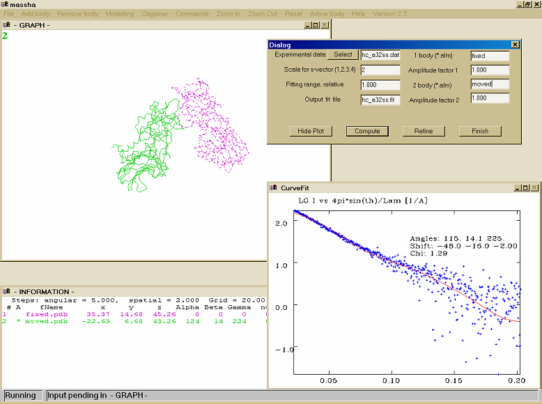 This menu item permits to perform interactive and/or automated rigid body refinement against scattering data. The scattering amplitudes of the subunits must be precalculated and saved in the current directory onto the files with the same names as the structure files (*.pdb or *.alm) with the extension "*.alm". This is performed by the program "FLM2ALM" for SLD-objects and by the programs "CRYSOL/CRYSON" for PDB-objects. HeterodimerHETERODIMER Rigid body refinement of a complex consisting of two unequal subunits (or equal subunits without assuming a 2-fold symmetry). These MUST be the first and the second loaded bodies The parameters to be specified: 1. Input data file -- Input file containing experimental data to be fitted. This name may also be selected with a file chooser by clicking on the "Select" option. 2. Scale for s-vector -- Abscissa units in the input file:
3. Fitting range -- Which portion of the experimental data to fit (as a fraction of sMax) 4. Output file --- The file containing the currently plotted fit 5,7. The *.alm file names of the first and the second subunits of the complex 6,8 The amplitudes of the 1st and 2nd subunit will be multiplied by these factors (e.g. contrasts) to compute the total intensity MASSHA warns the user if the given information is incorrect or incomplete. The "COMPUTE" button runs the program "alm22int", calculating the complex scattering intensity. The fit to the experimental data is plotted in a separate Curve Fit window and remains on the display at the user's disposal. The user may change positions of the two subunits by manipulating the objects in the 3D window and then recalculate the fit by clicking "COMPUTE". The user may move/rotate either the first or the second body, or both of them. The "REFINE" button runs the program "dimref" which performs an automated rigid body refinement around the current position. The position of the second subunit is varied around the current position by deltaX=deltaY=deltaZ=+-(Space Increment) (i.e. three points in each direction). The default increment is computed by MASSHA from the dimensions of the first body (see PARAMETER PANEL), can be changed by PARAMETERS -> Space Increment. The orientation of the second subunit is varied around its current orientation by rotating aroung X, Y and Z by +-2*(Angle Increment) (i.e. five points for each rotation) The default angle increment is 5 degrees, and can be changed by PARAMETERS -> Angle Increment. After the refinement, the fit is plotted and the refined position of the second body is displayed; its old position is also displayed as the third body. After the refinement, the user may manipulate the second body manually and press "COMPUTE", or re-launch "REFINE" from the current position. The user may also re-select the rotation center of the second body (see TRANSFORMATIONS) The structure of the entire refined heterodimer corresponding to the INITIAL position of the first body is saved onto a file "dimref.pdb". The "HIDE PLOT" button removes the CURVE FIT graphic window. The "CANCEL" button hides the dialog window. NOTE: When the rotation center does not coincide with the center of mass, minor deviations may be observed between COMPUTE and REFINE (due to termination effects) HomodimerHOMODIMER A special mode for rigid body refinement of a homodimeric complex assuming 2-fold symmetry. The monomer MUST be the first loaded body The parameters to be specified are similar to those for the HETERODIMER. The difference is that the amplitudes for the second body are automatically computed from those of the first body. To use the HOMODIMER option, load the first body, select it to be active and position it to the origin using the TRANSFORMATION option. Then move the body along X by -DX/2 where DX is the approximate distance between the monomers. After pressing HOMODIMER, the second momomer is generated automatically assuming Y to be the 2fold symmetry axis. Specify the parameters required (see HETERODIMER) with the exception of the second body amplitudes and factor. MASSHA warns the user if the information is incorrect or incomplete. The "COMPUTE" button runs the program "alm2in2" calculating the complex scattering intensity. The fit to the experimental data is plotted in a separate Curve Fit window. The user may change position/orientation of the first body and then recalculate the fit by clicking "COMPUTE". If the FIRST body is active, the second body is re-generated using the 2-fold symmetry transformation. NOTE: only rotations around the center of mass are allowed (the center residue is automatically reset to "0" in the HOMODIMER mode") If BOTH bodies are active, the entire dimer is moved/rotated. NOTE: only rotations around Y and movements along Y are allowed in this mode! The SECOND body cannot be active! The "REFINE" button runs the program "dimref2" that performs automated rigid body refinement around the current position. For the definition of the spatial and angular increments increments, see description of HETERODIMER. The position of the first subunit is varied aroung the current position by deltaX =+-2*(Space Increment) (a total of five points along X). The orientation of the first subunit is varied aroung the current orientation by rotating aroung X, Yand Z by +-5*(Angle Increment) (i.e. eleven rotations around each axis) After the refinement, the fit is plotted, the second body is re-generated from the refined position of the first one. The old position of the first body is displayed as the third body. The structure of the entire refined homodimer is saved onto a file "dimref2.pdb". The "HIDE PLOT" button removes the CURVE FIT graphic window. The "CANCEL" button hides the dialog window. Multibody (multidomain)MULTIBODY Before starting 'Multibody' modelling one has to select an active group of bodies which will be moved and/or rotated. This can be done with 'Active Body' menu, in this dialog box the user has to spesify the sequence of active bodies (using the following string: 1;2;4 etc., active bodies must be separated by semicolon), the rotation center can be the geometrical center of all selected bodies (if both body center=0 and residue center=0), or the geometrical center of one of the selected bodies (in this case body center>0, and residue center=0) or altenatively the specific residue of one of the selected bodies (in this case body center>0, residue center>0) 'Multibody' menu is designed for rigid body modelling of multi domain (or multi subunit) protein structures. It is possible to use up to seven loaded bodies. In the dialog box the following parameters must be specified: 1. Input data file -- Input file containing experimental data to be fitted. This name may also be selected with a file chooser by clicking on the "Select" option. 2. Scale for s-vector -- Abscissa units in the input file:
3. Fitting range -- Which portion of the experimental data to fit (as a fraction of sMax) 4. Output file --- The file containing the currently plotted fit 5. The *.alm file names of the different subunits of the complex 6 The amplitudes of the different subunits will be multiplied by these factors (e.g. contrasts) to compute the total intensity MASSHA warns the user if the given information is incorrect or incomplete. The "COMPUTE" button runs the program "groupref", calculating the complex scattering intensity. The fit to the experimental data is plotted in a separate Curve Fit window and remains on the display at the user's disposal. The user may change positions of the active subunits by manipulating the objects in the 3D window and then recalculate the fit by clicking "COMPUTE". The user may move/rotate either the one body, the selected group of bodies or all of them. The "REFINE" button runs the program "groupref" which performs an automated rigid body refinement around the current position. The position of the active selected group of subunits is varied aroung the current position by deltaX=deltaY=deltaZ=+-(Space Increment) (i.e. three points in each direction). The default increment is computed by MASSHA from the dimensions of the first body (see PARAMETER PANEL), can be changed by PARAMETERS -> Space Increment. The orientation of the second subunit is varied around its current orientation by rotating aroung X, Y and Z by +-2*(Angle Increment) (i.e. five points for each rotation) The default angle increment is 5 degrees, and can be changed by PARAMETERS -> Angle Increment. After the refinement, the fit is plotted and the refined position of the active group of bodis is displayed; its old position is also displayed by pressing button 'Load previous'. After the refinement, the user may manipulate the active group of bodies manually and press "COMPUTE", or re-launch "REFINE" from the current position. The user may also re-select the rotation center of the active group of bodies (see TRANSFORMATIONS) The "HIDE PLOT" button removes the CURVE FIT graphic window. The "CANCEL" button hides the dialog window. NOTE: When the rotation center does not coincide with the center of mass, minor deviations may be observed between COMPUTE and REFINE (due to termination effects) OLIGOMER (symmetry)OLIGOMER A special mode for rigid body refinement of a oligomeric complex assuming different types of symmetry (P2, P3, P4, P5, P6, P32, P42, P52, P62, P222). The monomer MUST be the first loaded body. The parameters to be specified are similar to those for the HETERODIMER. The difference is that the amplitudes for the second body are automatically computed from those of the first body according to the type of the symmetry. To use the OLIGOMER option, load the first body, select it to be active and position it in appropriate way. After pressing OLIGOMER and P?? symmetry, the second monomer is generated automatically assuming P?? symmetry. Specify the parameters required (see HETERODIMER) with the exception of the second body amplitudes and factor. MASSHA warns the user if the information is incorrect or incomplete. The "COMPUTE" button runs the program "almsymm" calculating the complex scattering intensity. The fit to the experimental data is plotted in a separate Curve Fit window. The user may change position/orientation of the first body and then recalculate the fit by clicking "COMPUTE". If the FIRST body is active, the second body is re-generated using the appropriate P?? (P2,P3,P4,P5,P6,P32,P42,P52,P222) symmetry transformation. NOTE: only rotations around the center of mass are allowed (the center residue is automatically reset to "0" in the OLIGOMER mode") If BOTH bodies are active, the entire oligomer complex is moved/rotated. The "REFINE" button runs the program "dimsymm" that performs automated rigid body refinement around the current position. For the definition of the spatial and angular increments increments, see description of HETERODIMER. The position of the first subunit is varied aroung the current position by deltaX =+-2*(Space Increment) (a total of five points along X). The orientation of the first subunit is varied aroung the current orientation by rotating aroung X, Yand Z by +-5*(Angle Increment) (i.e. eleven rotations around each axis) After the refinement, the fit is plotted, the second body is re-generated from the refined position of the first one. The old position of the first body is displayed as the third body. The structure of the entire refined homodimer is saved onto a file "dimsymm.pdb". The "HIDE PLOT" button removes the CURVE FIT graphic window. The "CANCEL" button hides the dialog window. TransformationsThe TRANSFORMATIONS submenu in the COMMANDS menu performs absolute/relative shifts and rotations of the objects The action will be applied to the currently active body. X0, Y0, Z0-center : coordinates of the rotation center of the object Alpha, Beta, Gamma: Euler angles of rotation Absolute shift : clicking on this button will rotate the object by Euler angles Alpha, Beta, Gamma and move it so that its rotation center will have the coordinates X0, Y0, Z0 Relative shift : clicking on this button will rotate the object by Euler angles Alpha, Beta, Gamma and move it by X0, Y0, Z0 from its current position Residue: the number of residue whose coordinates define the current rotation center of the object. If "0", the center is given by the coordinates of the center of mass. Relevant for PDB-objects only. Active body: ordinal number of the currently active body Zero means that ALL bories are active. NOTE: to implement the spatial transformation, the user MUST click either "Absolute shift" or "Relative shift" button. The "Apply" button changes only the Residue and the Active body assignments. To discard the changes, click "Finish". The button "Finish" MUST also be used to terminate the dialog and return to the 3D window HINT: To return an active object to its initial position use the menu option RESET. If ALL ojbects are active, they will all be reset. The command RESET also resets the rotation center to the center of mass! ALIGN PDB This command aligns two PDB objects. The second body is moved and rotated to best match the first one by running the program SUPREF (Kozin & Svergun, 2000).No information about correspondence between the points in the two bodies are required. The number of CA or P atoms in the two objects can be arbitrary (but not less than two). The second object is replaced with the object named aligned.pdb and displayed as the second body. You may modify the position of this body manually and run the program and again again (the name will be "align0.pdb", then again "align.pdb" and so on). The result can be saved using the Save PDB option under the name "phsave2.pdb". NOTE: the program minimizes "normalized spatial discrepancy" (NSD) starting from the current position of the second body. As SUPREF can be trapped in a local minimum, it is recommended that this initial approximation is properly selected by visual criteria. ZoomingThe graphic library used to write MASSHA does not permit to ressize windows by dragging their corner by a mouse. To change the size of the 3D graphic window, the buttons Zoom In/Zoom Out are provided. They will change the physical size of the 3D window as opposed to the hotkey commands F5/F6 (the latter commands zoom in/out the 3D picture inside the fixed frame. HINT: The commands Zoom In/Zoom Out may also be useful if the 3D window remains inactive and the hotkeys seem not to work. This may happen from time to time on due to problems with windows focus transfer. Using Zoom In/Out may help to 'reanimate'the 3D window. TroubleshootingKnown problems, date 25/09/09: - If the graphics window does not want to be active (hotkeys do not work) try pressing Zoom In/Zoom Out - If MASSHA is started with the files loaded from the command line, the graphics window may show a slower response. The effect is removed by Zoom In/Zoom Out - In some cases, first hotkey is ignored when returning from a Modelling dialogue to the 3D graphic screen - During "Modelling" the following programs are called from MASSHA to calculate the current fit or to make local rigid body search. If you are using HETERODIMER: program "Alm22int" is called to calculate the current fit to the data program "Dimref" is called to perform local rigid body search If you are using HOMODIMER: program "Alm2int2" is called to calculate the current fit to the data program "Dimref2" is called to perform local rigid body search If you are using MULTIBODY: program "Groupref" is called to calculate the current fit to the data and to perform local rigid body search If you are using OLIGOMER: program "Almsymm" is called to calculate the current fit to the data program "Dimsymm" is called to perform local rigid body search It is possible to check/debug these programs by running them from the command line "ProgramName.exe ProgramName.cmd" and check the corresponding "ProgramName.err" files. - if the program (MASSHA) was terminated abnormally when using Modelling, processes Alm22int, Dimref, Alm2int2 or Dimref2 may hang in memory and should be removed manually. Also, some auxiliary files (dimref.err), normally deleted by Massha, may be kept and they also should be removed manually, otherwise, the modelling would not work in this directory! - if no object is displayed, don't panic, check the following things: 1) press F4 (check the position of the center, and the number of atoms that were read, it should be > 0 ) 2) If the structure is displaced far away from the center, use zoom out button F6 (several times if necessary) 3) There are two modes representing PDB files (by chains or by circles) Default option is "chain" mode, which will connect "CA" (or "P") atoms if the distances between them are less than 5 (or 8 ) Angostrom respectevely. One can change this limits from "Commands" menu, changing Rmax(CA) and/or Rmax(P) edit boxes. For ab initio (DAMMIN/DAMMIF) models it is recommended to switch the mode to "circles" by pressing F3. |
||||||||||||||||||||||||||||||
Last modified: April 11, 2013
© BioSAXS group 2013